


LESSON OVERVIEW
What brings 3D worlds to life, literally piece by piece? 3D models! They are the foundation of everything you see in games and animation, from the smallest pebbles and scattered props to vast cities. 3D modelling is the process of creating these objects, building them up from simple shapes into fully realised assets that can be textured, lit, and animated. Whether it’s a weapon in a first-person shooter or a tree in an open world game, it all starts with a model.
In this lesson, we’re introducing the core concepts of 3D modelling and how a 3D model is constructed. The aim of this lesson is to get comfortable with key terminology, understanding how shapes are built, how surfaces are formed, and how to begin thinking like a 3D artist.
By the end, you’ll have a solid grasp on the fundamental building blocks of 3D game art, and a clear understanding of how to approach modelling with clean, efficient topology. You’ll also begin to recognise the importance of structure, silhouette, and form in creating models that not only look good but also function well.
WHAT IS A 3D MODEL?
A 3D model is a virtual object representing something within 3D software. It can be anything from a chair to a character, or even an entire building. 3D modelling is used in many industries, including video games, film, architecture, product design, medical visualisation, training simulations, and 3D printing, just to name a few.
There are several ways to create 3D models. These include CAD (Computer-Aided Design), voxels (3D Pixels), sculpting and polygon modelling.
In this lesson, we’ll focus entirely on polygon modelling, the process of building models using vertices, edges and faces to define the shape of the object. It’s a versatile and widely used approach, especially in game development.
SOFTWARE
3D software is just a tool - using a specific software won’t make you a good artist, but the right tool can make your job easier. Fundamental skills and core concepts remain the same between software packages; processes may change, but building a good foundation is key.
The three most common modelling software used across the games and film industries, as well as hobbyists, are Autodesk Maya, Autodesk 3ds Max and Blender. 3D software is often referred to as DCC (Digital Content Creation) software.
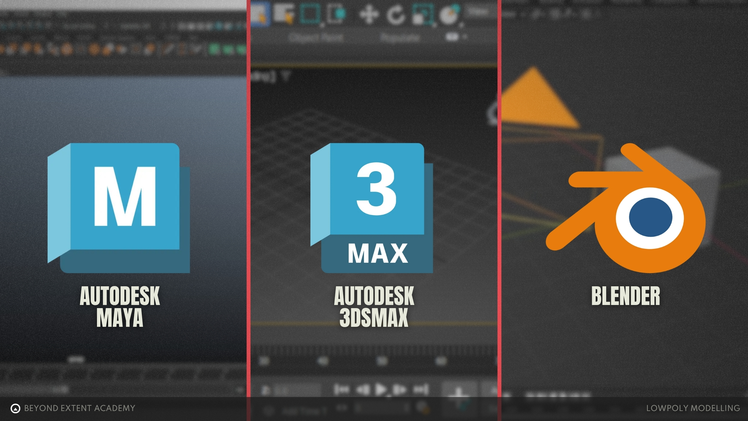
While Maya, 3ds Max and Blender are versatile and are capable of many tasks, they each have different workflows, interfaces and strengths!
MAYA is a well-rounded 3D package with strong direct modelling tools. It’s a staple in both film and game development pipelines thanks to its deep toolset and integration with animation and rigging workflows. Maya is a paid software, though free educational licenses are available for students at accredited institutions.
3DS MAX excels at hard surface modelling and environment design. Its powerful modifier stack allows for non-destructive workflows, making iteration and design changes easier. It’s widely used in game development and architectural visualisation. Like Maya, 3ds Max requires a paid licence, with educational access available for students too.
BLENDER blends aspects of both Maya and 3ds Max. It supports direct modelling as well as modifier-based workflows, and is known for being beginner-friendly thanks to its community and open-source, free licence. While some of Blender’s advanced features may not be as deep as those in Maya or Max, its modelling tools are fast, capable and improving rapidly. Blender is increasingly being adopted across games and film.
Specialised Software
Most modelling will start in the general-purpose DCC software as discussed above, which will be able to perform the majority of tasks any 3D artist will ever need to do. Sometimes though, there is a need to perform certain tasks more efficiently — this is where our specialist software comes in. For example, it’s possible to model any form of vegetation within Blender, however, Speed Tree is a purpose-built software designed to allow artists to generate complex vegetation with node-based workflows. Hard surface art is easily done using 3ds Max’s toolsets and modifier based approach, however using CAD software such as the relatively new Plasticity has allowed hard surface artists to leverage the precision of CAD with an artist friendly interface — this allows artists to generate complex non destructive shapes that would be very difficult to do via traditional polygon modelling. All three of the common DCC software packages include some form of cloth simulation toolset however, Marvellous Designer was built to be a specialist in cloth creation and simulation.
We won’t touch on any specialised software in this lesson, but it’s handy to start to think of software as tools on your toolbelt!
For the remainder of the lesson, all examples and exercises provided will be using Blender 4.26. The content will aim to be as transferable as possible, focusing on fundamental skills that can be done in any DCC package.
COORDINATE SYSTEMS
3D Space
In 3D modelling software, everything exists within a three-dimensional space. To identify the positions of each vertex, we use a coordinate system made up of three axes known as the Cartesian coordinates: X, Y, Z. In Blender, these refer to Left/Right, Front/Back and Up/Down, respectively.
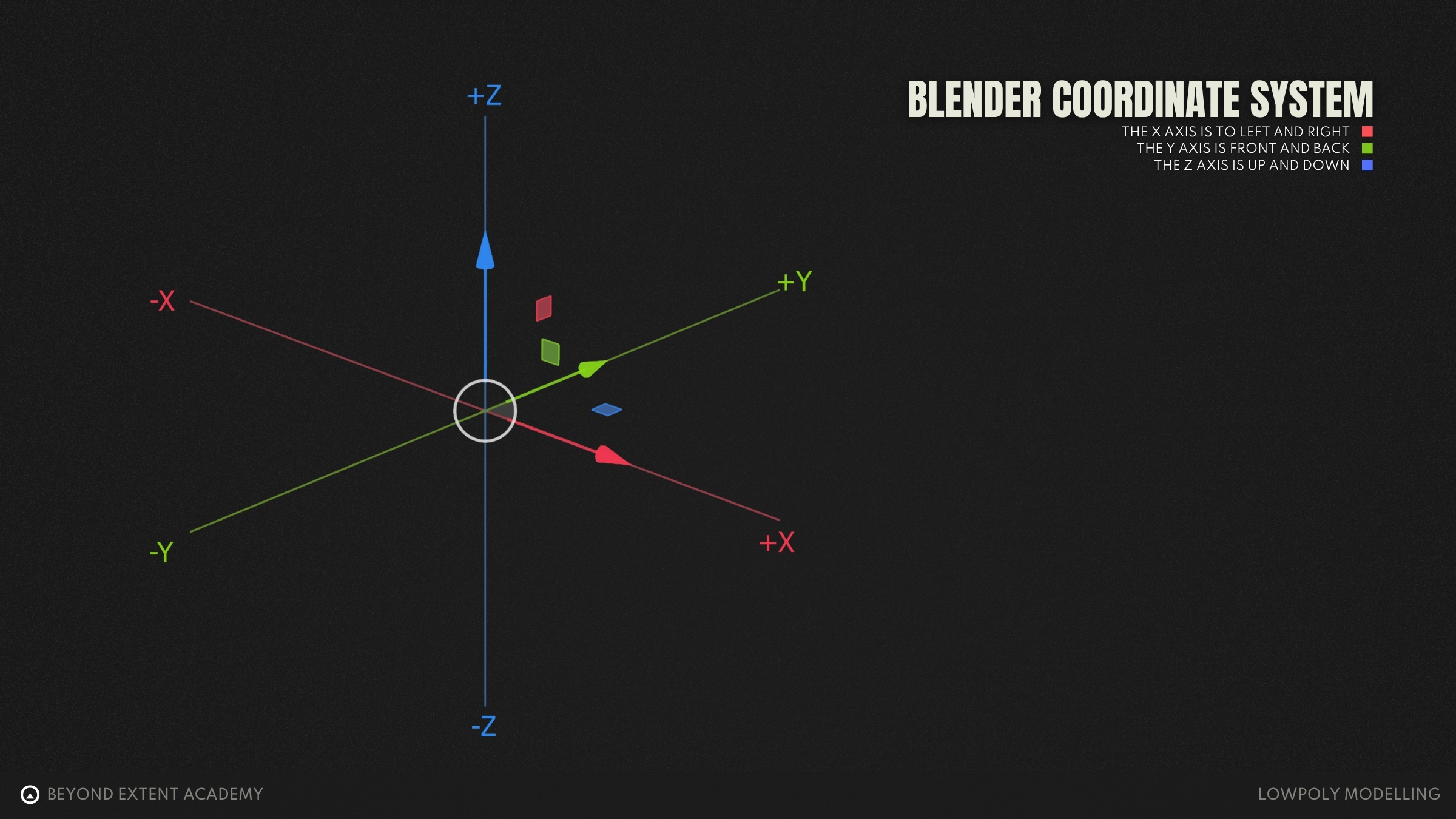
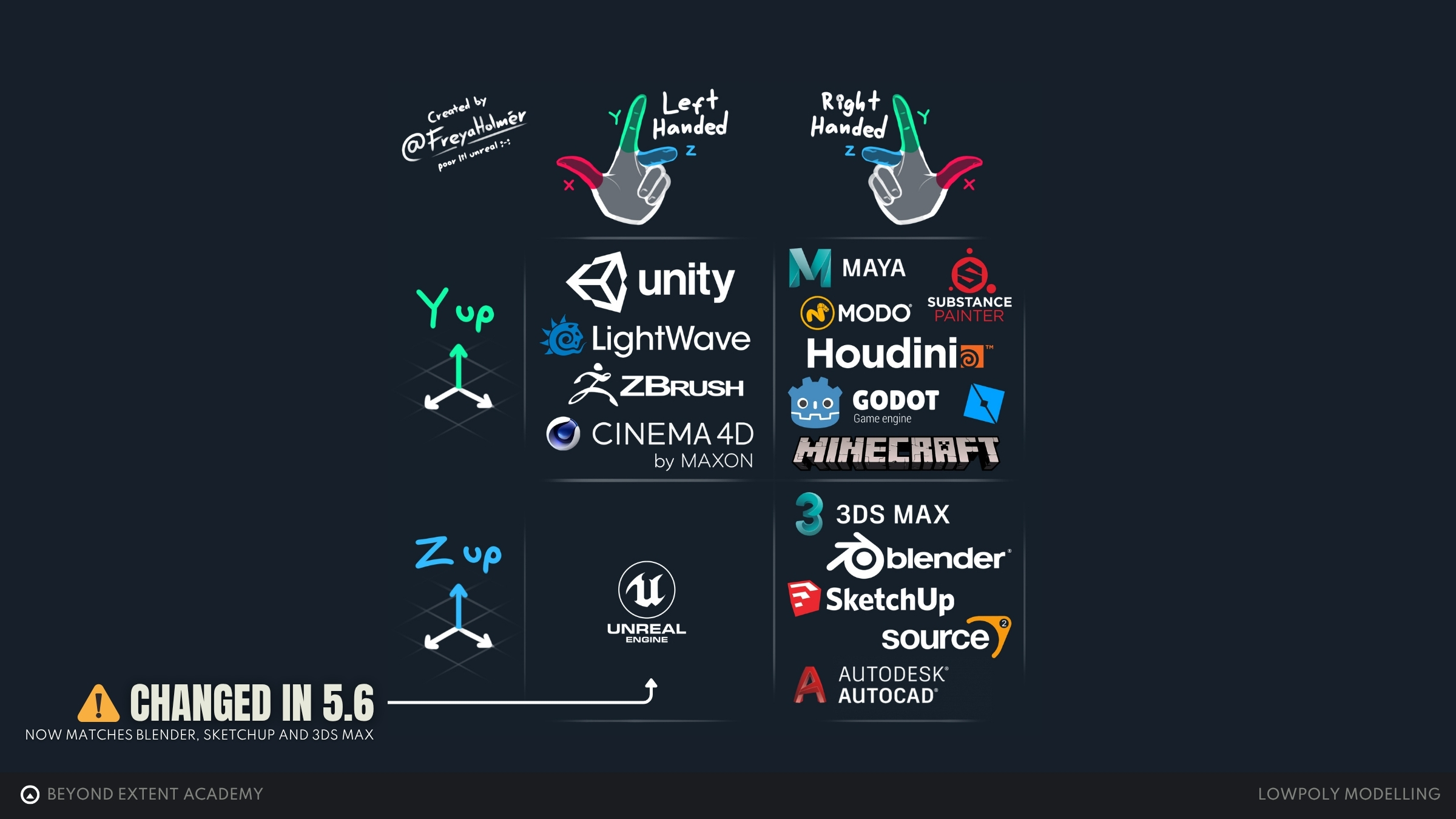
Different 3D software uses different coordinate systems, which can affect how models appear when moved between programs. These seem complicated at first, so let’s break them down:
- Y-up vs Z-up
- - which axis points upward
- Left-handed vs right-handed
- which direction the forward axis (Z or Y) points
In a Y-up system
- Right-handed: +Z is forward, +X is right
- Left-handed: +Z is backward, +X is right
In a Z-up system
- Right-handed: +Y is forward, +X is right
- Left-handed: +Y is backward, +X is right
Viewing your model
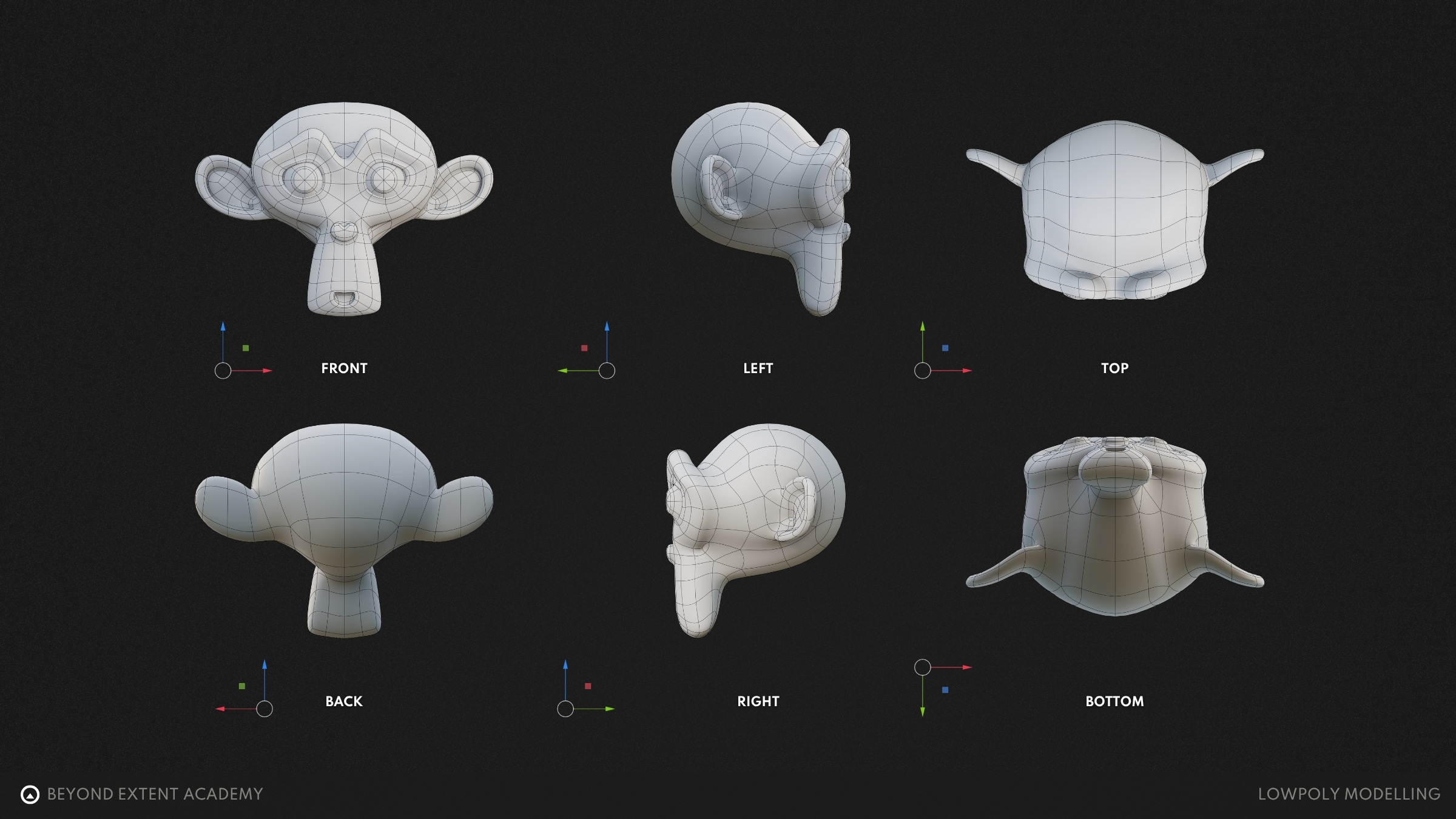
In our DCC software, the viewport is where we see our model and perform all of our modelling operations. It offers several ways to view and work with your model, each suited to different tasks. One of the most useful sets is the orthographic views: front, back, left, right, top and bottom. These are all aligned with the previously discussed Cartesian coordinate system and show the model without any distortion. Everything will be flat and aligns to scale, which makes them ideal for precise modelling, snapping and working with reference images.
As well as these fixed views, there’s also the 3D view. This lets you move around your model freely and can be set to either perspective or orthographic mode.
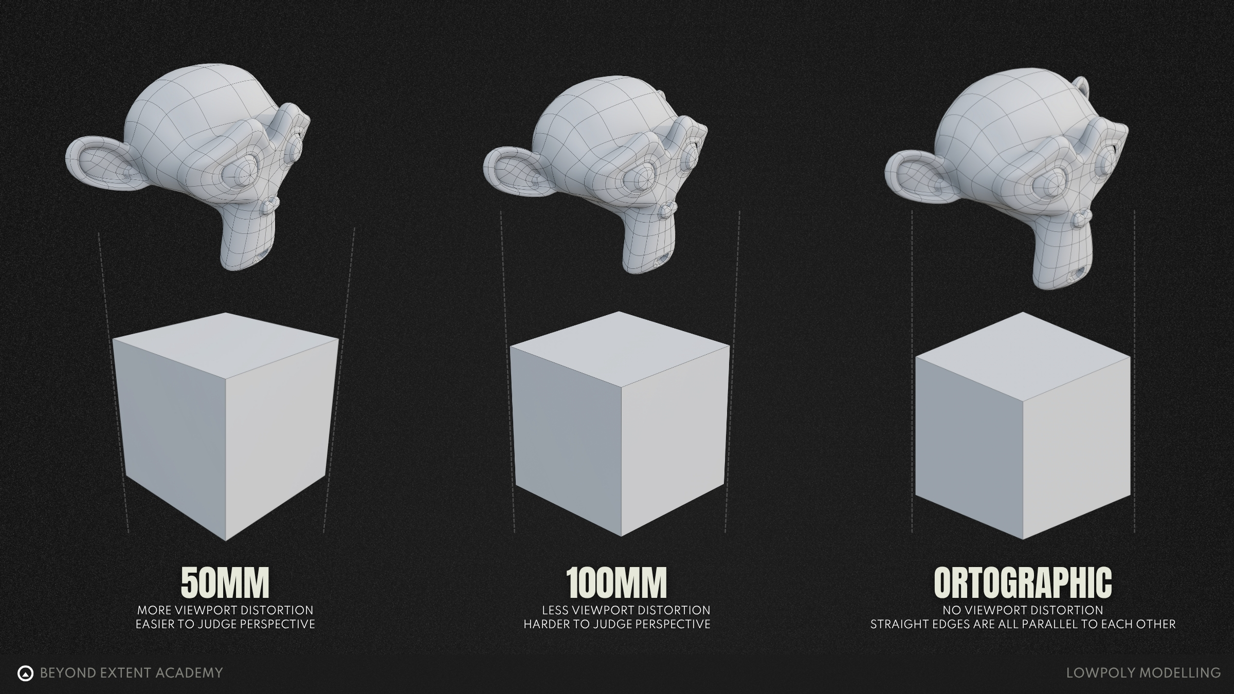
Perspective view will mimic the way that we see objects in the real world, objects that are further away appear smaller and have a sense of depth. It’s perfect for seeing how a model may look in context, such as in-game. Perspective view in DCC software will often allow you to modify the FOV (Field Of View), which controls how wide or narrow the “camera sees” in a 3D scene; it will affect perspective distortion and can change how a model appears.
Orthographic views will eliminate any perspective distortion, all objects remain the same size regardless of depth. This is often used for accurate modelling, where components need to be aligned and to check proportions correctly. Orthographic will feel quite unnatural, but it makes it far easier to model technical shapes or to reference imagery.
ANATOMY OF A 3D MODEL
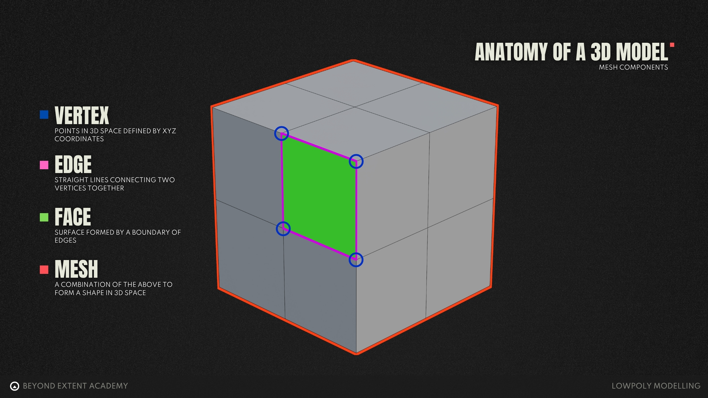
A 3D model is made up of 3 basic components. These are vertices, edges, and faces. Together, these elements form the structure of the model, often also referred to as its geometry. Geometry is simply the shape and form of the model, built from these connected components.
Vertex
A vertex (or vert) is a single point in 3D space, defined by X, Y and Z coordinates. Vertices don’t do too much on their own, however, they form the backbone of the entire mesh and can store useful attributes such as normals.
Edges
An edge is a straight line that joins two vertices. These form the wireframe of the model, which is often overlayed onto a model in the DCC software and displays the model’s topology.
Polygons (Faces)
A polygon, also known as a face, is a flat surface that is formed by connecting at least three edges. Polygons can be further categorised as triangles, quads and ngons, but more on that later.
The Mesh
When we use all of the above together to form a shape in 3D space, we get a mesh! A 3D model can be made up of multiple mesh components. For example, the wheels and the body of a car would be separate meshes that are combined into a single model of a car.
Rings and Loops
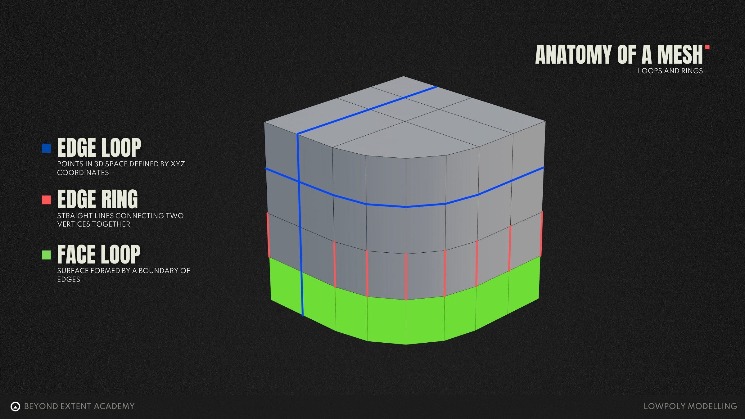
Loops and rings are ways of selecting and organising polygons and edges in a 3D model. A loop is a continuous line of selected edges or polygons that usually flows around a model. A ring is a series of edges that run perpendicularly to a loop. Both of these are important aspects of a 3D model. When making characters, loops will follow the flow of muscles and joints - they are critical to allowing the mesh to bend naturally during animation. On a human face, these loops are commonly found around the mouth and eyes.
Normals
Each vertex and face on a 3D model has an attribute called a normal. You can think of normals as invisible lines that indicate which direction a surface is facing. They don’t affect the literal shape of the model, but they play a critical role in how lighting and shading behaves. 3D software uses this information to calculate how light should interact with the model, which directly affects its shading and how it appears when rendered.
Face Normals
Each face has a single normal, that points straight out from the centre of the face, perpendicular to the faces surface. These let the software being used to render the model know which direction that surface should face. Every face will have a single normal, and this is consistent across the whole face.
If a face is flipped, its normals point inward which will cause lighting errors or make the face invisible in game or renders.
Vertex Normals
Vertex normals are calculated by averaging the face normals of all the faces connected to a vertex. When multiple faces meet at a vertex, the 3D software will take their normals, add them together and scales the resulting normal create a smooth, averaged direction. This becomes the vertex normal.
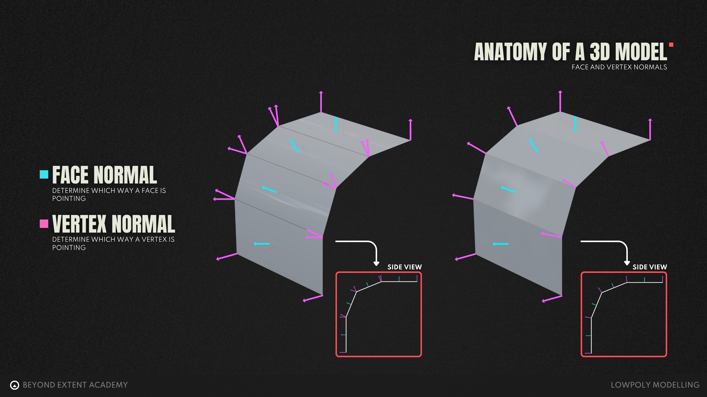
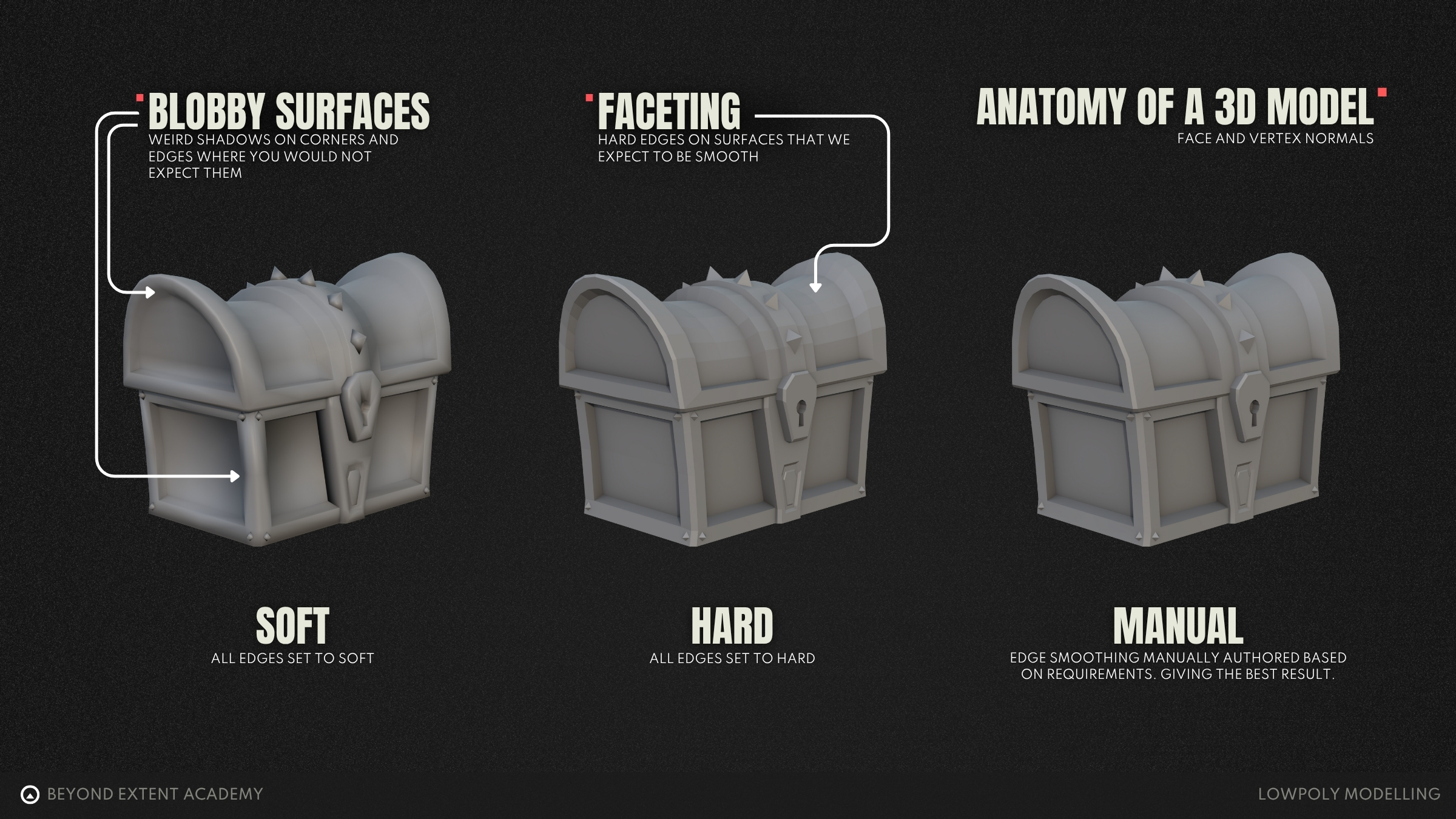
These are important, as vertex normals control how light interacts with a surface. If the normals are smoothly averaged, the shading will appear soft and “curved”. Vertex normals can also be kept separate between faces which can break the smooth shading, creating a hard, faceted look on edges. This is often referred to as hard and soft edges.
In most DCC software, we can control this behaviour manually — in Maya we can set hard and soft edges, in 3ds Max it’s managed per face via smoothing groups, and Blender can use auto smooth to set sharp edges or by marking edges as sharp.
With well managed normals, you can make a relatively low-poly model appear smooth in the right places, and preserve crisp, defined edges without needing to add additional geometry. In game development, this is key as we’re always trying to operate as efficiently as possible. Most game engines also use a technique called backface culling, where any face normals that are pointing away from the camera won’t be rendered to save resources. Correct normals are also essential when it comes to baking high resolution models to a texture from a high poly model. If the low poly mesh has broken or inconsistent normals then the bake will likely contain seams and bake errors. Check out these lessons for more information on [high poly modelling lesson] and [baking lesson]
TOPOLOGY
Topology refers to how the vertices, edges and polygons of a mesh are constructed and arranged. For the sake of simplicity we will keep this section about topology within modelling generic, however it’s worth noting that “good” topology can be subjective depending on the use case and workflow we will be using, to give an example: what may be considered good topology when modelling a character, would be considered bad topology for a rock. Or when modelling for 3D printing, the models topology would be required to be watertight, but for games this does not matter as much.
What does WATERTIGHT mean?
the model is completely sealed, there are no disconnected edges. Every face will connect perfectly to its neighbours, so if you were to fill the model with water (in theory), nothing would leak out no matter how you rotate the model.
Triangles, Quads and Ngons
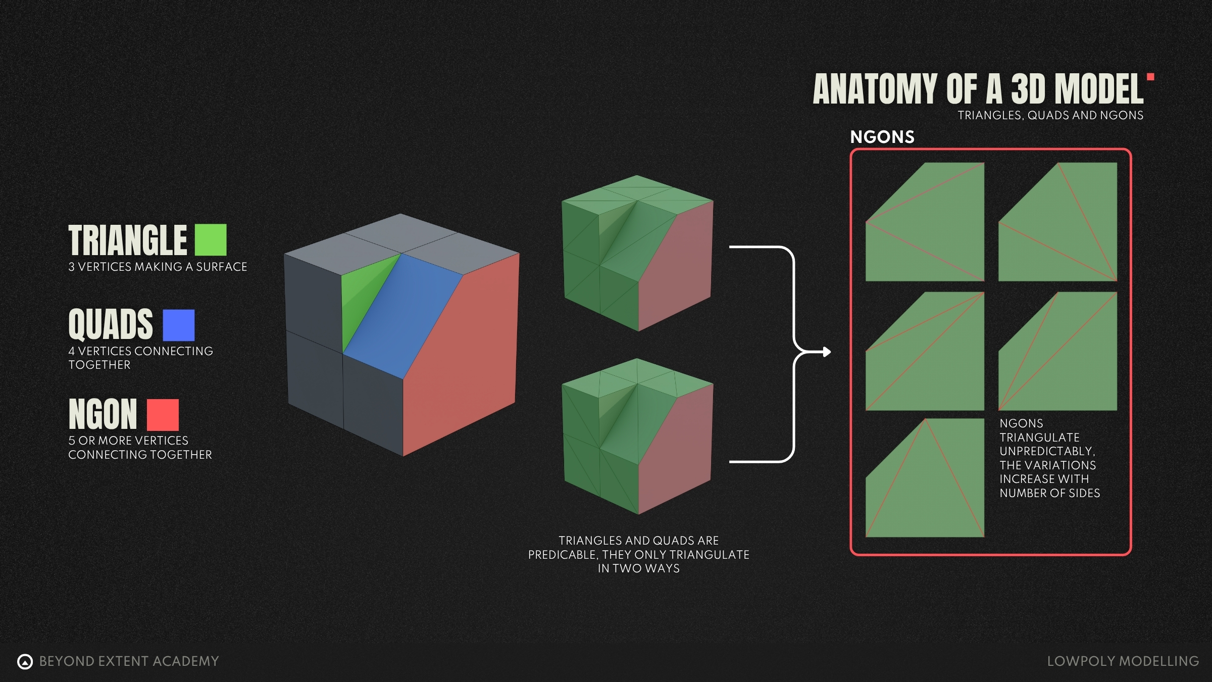
Each polygon can be further defined as one of the following: triangle, quad or ngon. This is entirely based on the number of edges that form the boundary of said polygon.
A triangle (tri), as you’d expect, is a polygon that is formed of three boundary edges. Triangles are the backbone of 3D rendering for games, every model you make will eventually be triangulated either on export from your DCC or on import to the game engine. This is because they are the simplest polygon - no matter how the vertices are oriented, the polygon formed will always be flat and unambiguous, making it efficient to render.
Quads are the next step up in terms of edge count, these are polygons made up of 4 edges. These are the most common polygons that you’ll use whilst 3d modelling. They are ideal for most modelling tasks due to them naturally supporting loop-based topology. Edge loops can flow smoothly around your models using quads, which makes it easier to form shapes and add detail, as well as build up complexity.
Ngon is a term for all polygons that are made up of five or more boundary edges. Software does support them, however, they can cause shading issues or break completely in game engines due to unpredictable triangulation. As seen in the below gif, there are many ways to triangulate an ngon, as you increase the number of edges, the number of potential triangulations increases, hence the unpredictability. Ngons do have a use case, specifically only when a surface is flat and will not be subdivided.
While there are general best practices in modelling, like using quads for clean topology and avoiding ngons on curved surfaces, it’s important to remember that these rules are contextual, not absolute. What’s considered to be “correct” can change depending on project, software, final use of the model, as well as peoples opinions and experiences. For beginners, we recommend sticking to mostly quads and using triangles carefully, as this will help you build clean, reliable models and avoid lots of common pitfalls. It’s important to build a solid foundation first, that aligns with how most pipelines may work. However, don’t let that stop you from experimenting as you begin to build confidence. In short: follow the rules to understand them, then test their limits to grow.
Now we have explored what topology is, we can start to look at how to operate with good, clean topology. Good topology in it’s simplest form means that your mesh is built in a way that cleanly supports the shape that you’re intending to represent, whilst remaining easy to edit.
This can be boiled down to a few key rules that can be followed: Use only as much geometry as you need
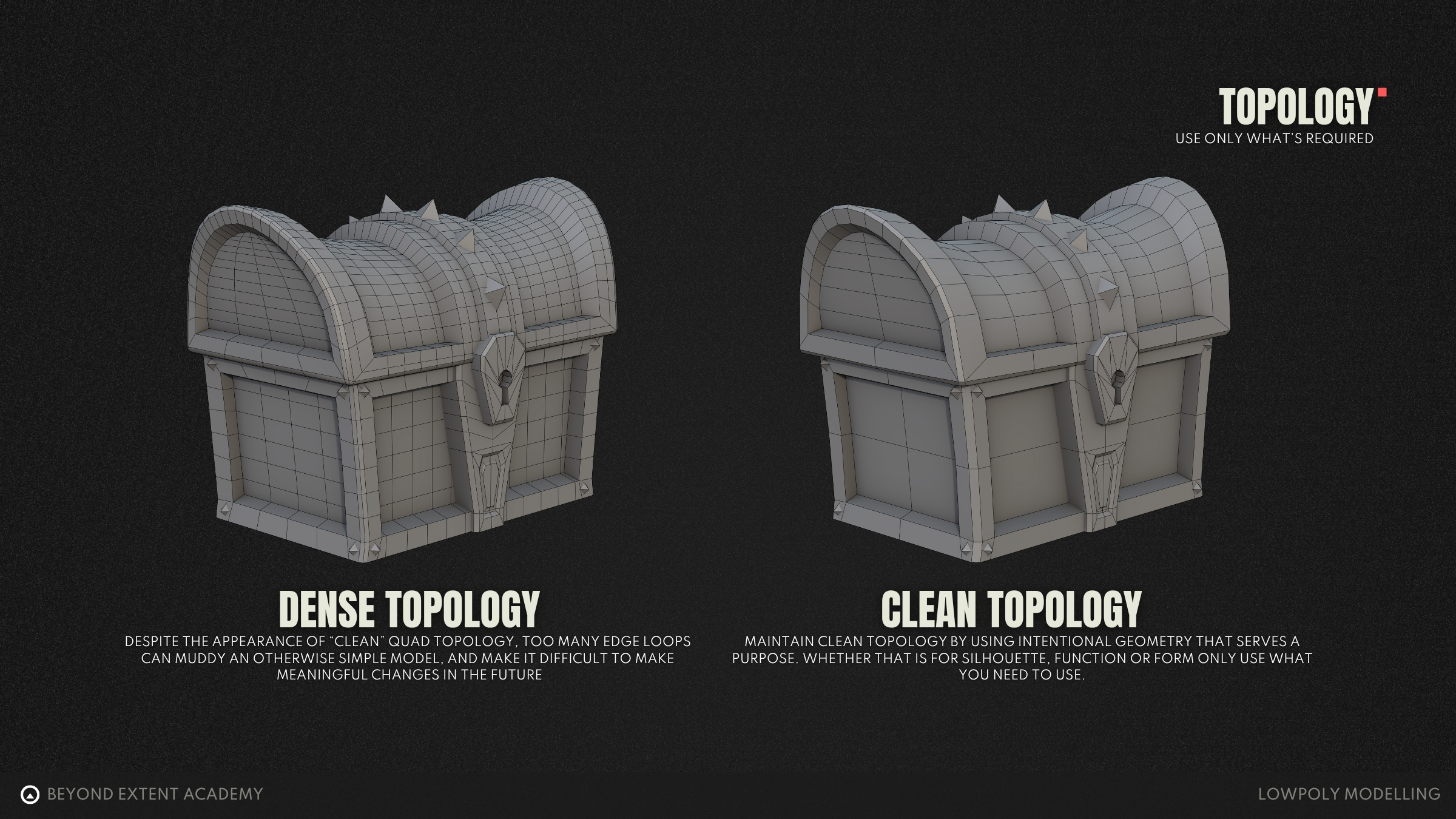
When modelling it can be tempting to use a lot of geometry to create your shapes - the caveat here is that too many edge loops can get complex and messy really quickly. It’s worth asking yourself often when modelling, “is this edge loop necessary for the model?” — if the answer is no, then it can be removed or merged with another. This helps to optimise our models too - each polygon comes at a “cost” to our GPU’s and to diskspace. Whilst polygons are pretty “cheap” nowadays, it’s good practice to give our GPU’s room to breath where possible by keeping our models lightweight, with the added benefit of making our models far more easy to view and edit.
Maintain even spacing
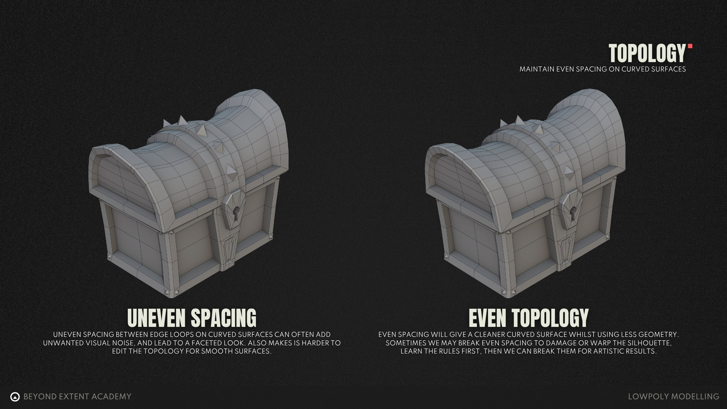
When working with curved surfaces, it’s important to maintain an even spread of topology. This helps to ensure that the surface appears smooth and clean, without bumps, pinching or distortion. Even quads will help the surface deform more predictably and will make it easier to control shading. That said, as with almost all rules in 3D modelling, there are times when it is perfectly fine to break this — for example, to sharpen a curve, or introduce intentional stylisation.
VISUAL MODELLING CONCEPTS
Reference Images
We often think we know what something looks like until we try to draw it from memory. Suddenly, shapes blur, details disappear, and proportions fall apart. The same happens in 3D modelling.
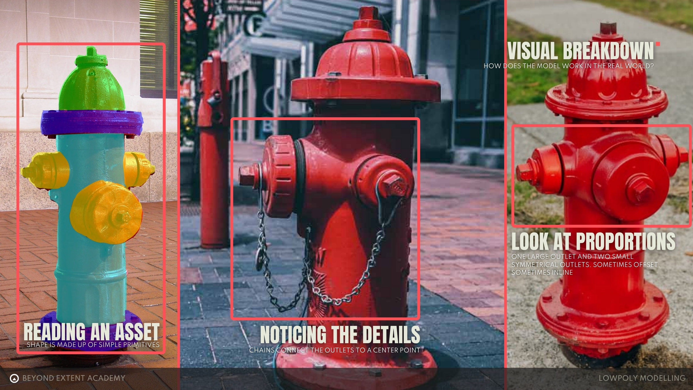
Good reference images are your visual anchor, they remove any guesswork and give you clarity as well as direction. When looking at reference, look for proportions, function, and what makes that object recognisable.
Using reference isn’t about copying or cheating, it’s about breaking your objects down into simpler forms, understanding the design and staying intentional throughout the modelling process.
For more information on gathering and using references, check out the lesson on REFERENCE GATHERING
Functionality
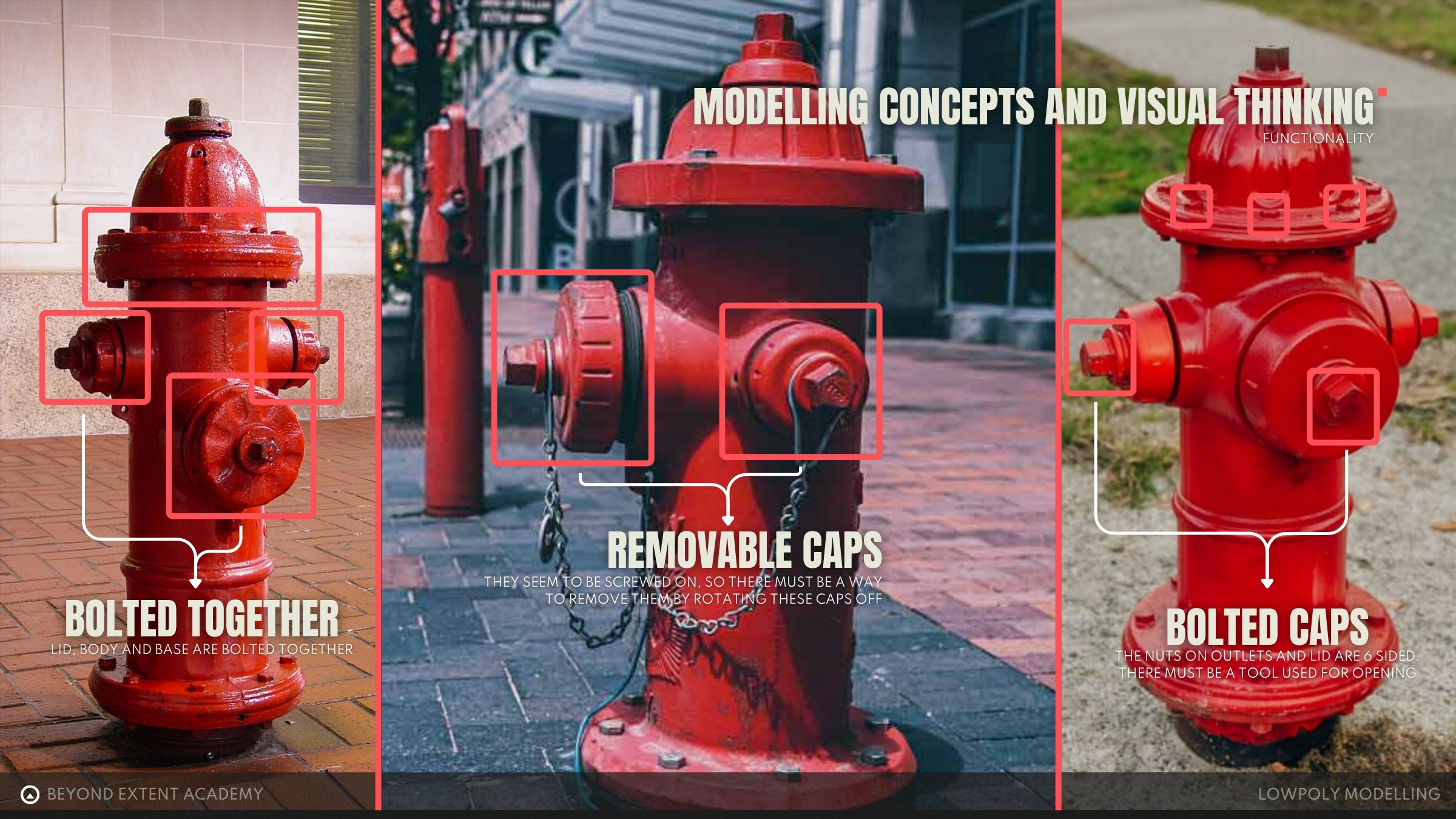
By studying the reference images, we can begin to understand how the object works in the real world. This helps us break down how the model might be built in 3D and adds a layer of believability to the final result, grounding it to reality.
Depending on the purpose of the model, we don’t always need to include every detail or complex mechanism. But having a clear grasp of how it functions will allow us to make smart decisions about which features to prioritise — modelling only the details that best convey how the object works.
Primitive Breakdown
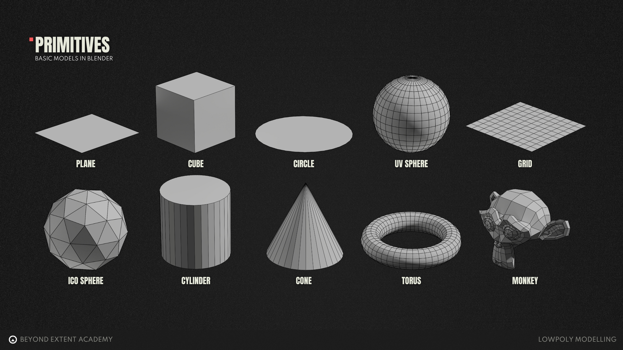
Almost everything that has ever been modelled in 3D starts with one or more simple shapes known as primitives. These are the basic building blocks that come packaged with every DCC software. Common examples include cubes, cylinders and spheres. These will act as your starting point for creating any object.
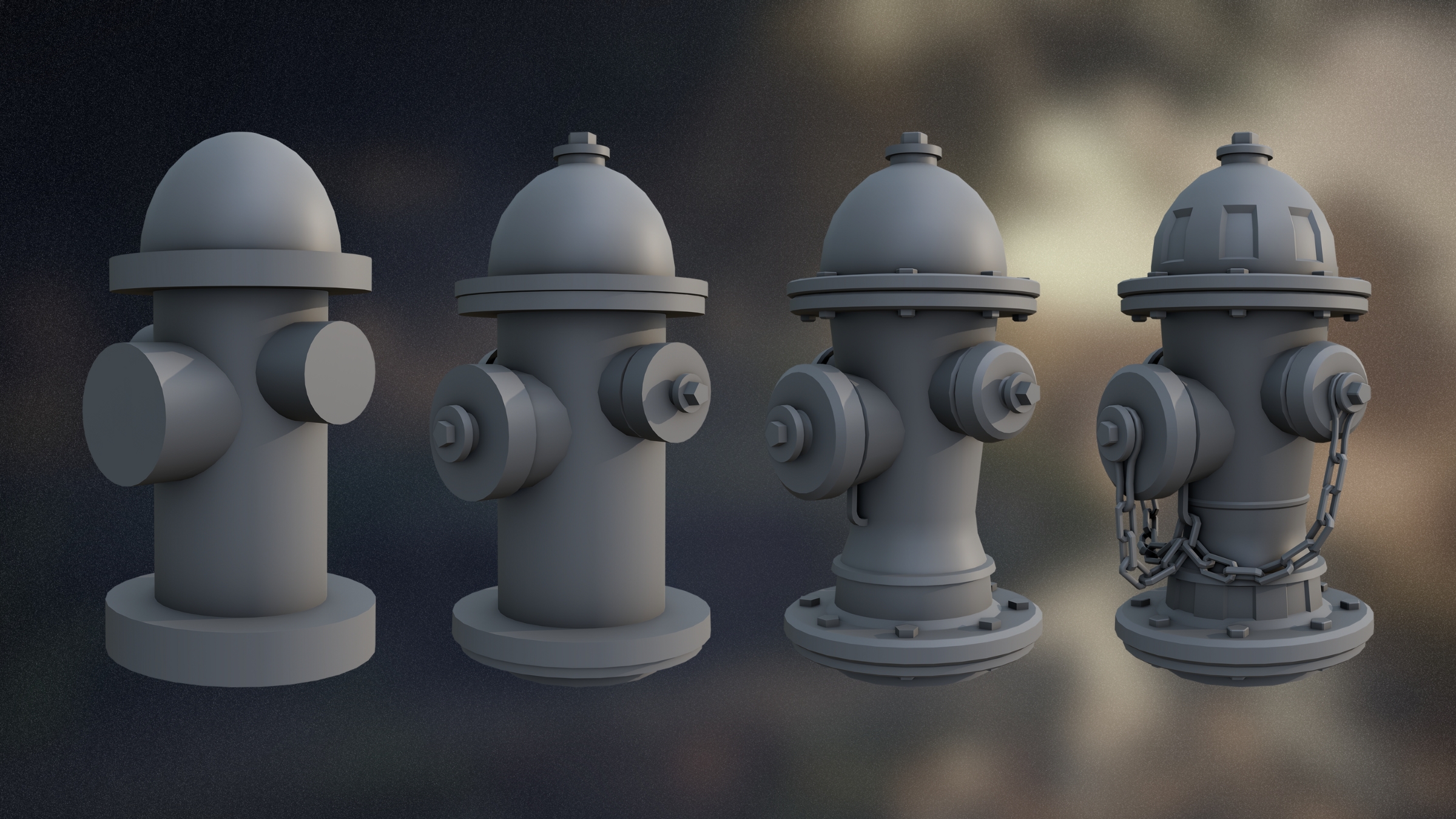
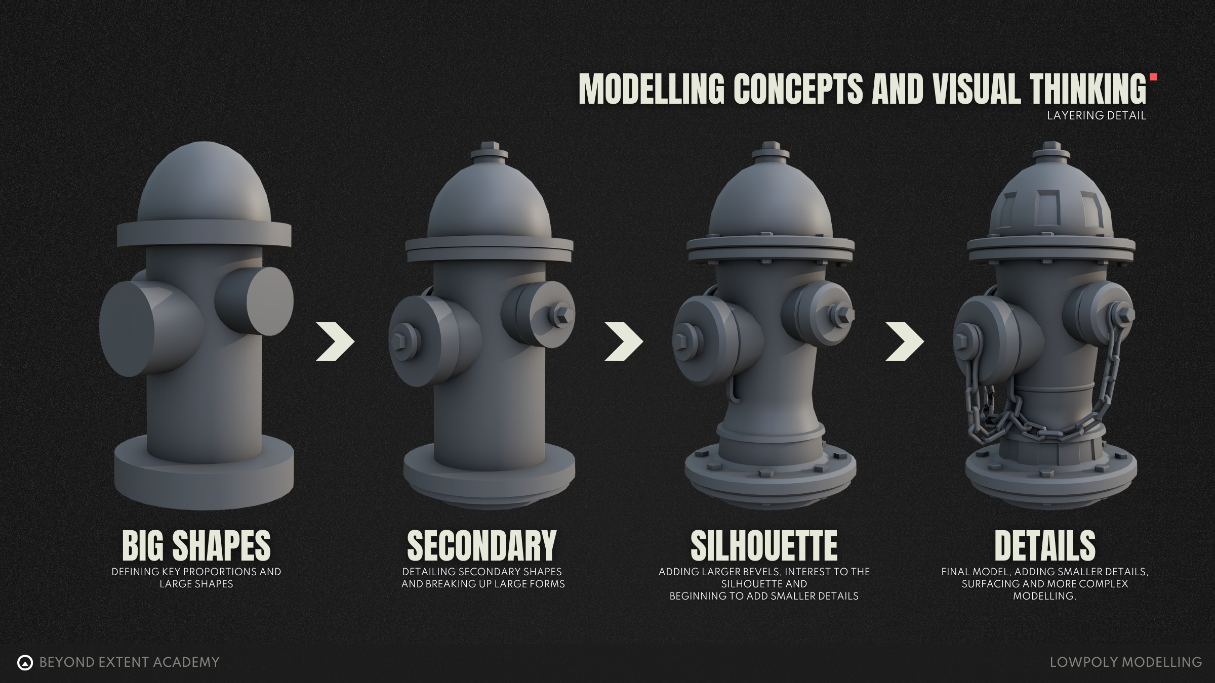
A large part of learning to model is learning how to see in 3D and break down real-world objects into their simplest forms. For example, a fire hydrant in its absolute simplest form could be broken down into some cylinders and a sphere for the top!
Building Up Detail
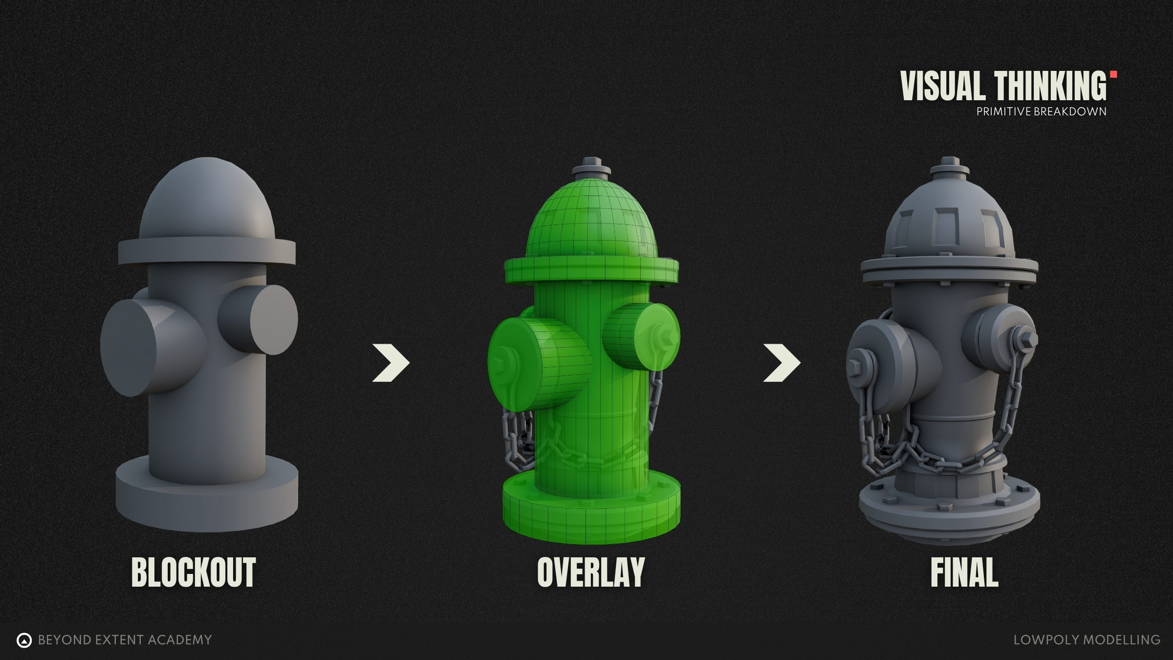
Once you start combining primitive shapes, you can quickly block out a model in 3D space. A blockout is a simplified version of your model where you establish the major components, correct scale and overall proportions based on your reference.
As a beginner (or even experienced artist), it can be tempting to jump straight into adding detail and trying to make your model look polished from the start, but skipping the blockout stage often leads to problems later on, especially with scale, proportion, silhouette and overall function. These are core elements that should be figured out early, when they’re easiest to adjust.
A solid blockout acts as a foundation. From there, it’s easier to add detail in layers, starting with the largest shapes and gradually refining down to smaller elements. This approach keeps your model consistent, prevents you from getting stuck on one area and helps maintain a strong form.
This layered workflow also helps to break the modelling process up into manageable steps. It’s a natural way to pause, check your progress, or ask for feedback. If there’s an issue with a major shape, it’s far, far easier to fix at an earlier stage than after you’ve spent hours refining details.
So, always start by breaking your object down into simple shapes, then build up detail progressively.
COMMON MODELLING TECHNIQUES
As mentioned prior, in their simplest forms… almost every single object can broken down into primitives. So lets start there! Every DCC software will include all of the basic primitives that you require for modelling. In Blender, we can add primitives with through the Add menu, and selecting Mesh. Here, we have access to all of the simple meshes that Blender offers, as well as grid and monkey, which are unique to Blender. 3ds Max also offers the Utah Teapot, which is a famous standard test model in 3D graphics history!
Once a primitive mesh is added to the scene, we can start shaping it by using a variety of modelling operations. Each of these tools performs a simple task, such as adding new faces or modifying edges and often come with settings to control how they behave. Most 3D modelling workflows are built by combining and repeating these operations, gradually turning basic shapes into detailed, refined models.
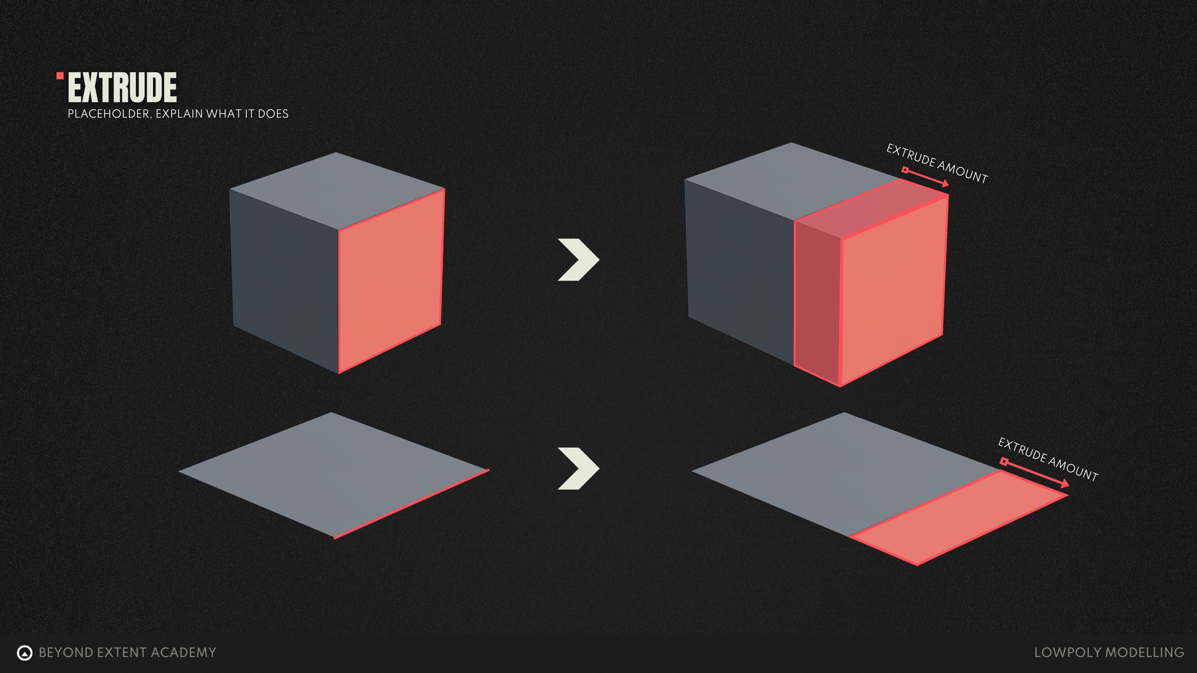
Extrude
The extrude tool lets you create new connected geometry by pulling out from selected faces, edges, or vertices. It’s great for adding thickness or extending shapes from a base mesh. If you're extruding from a flat plane, it won’t be watertight — you’ll need to use a tool like Bridge to close the open sides.
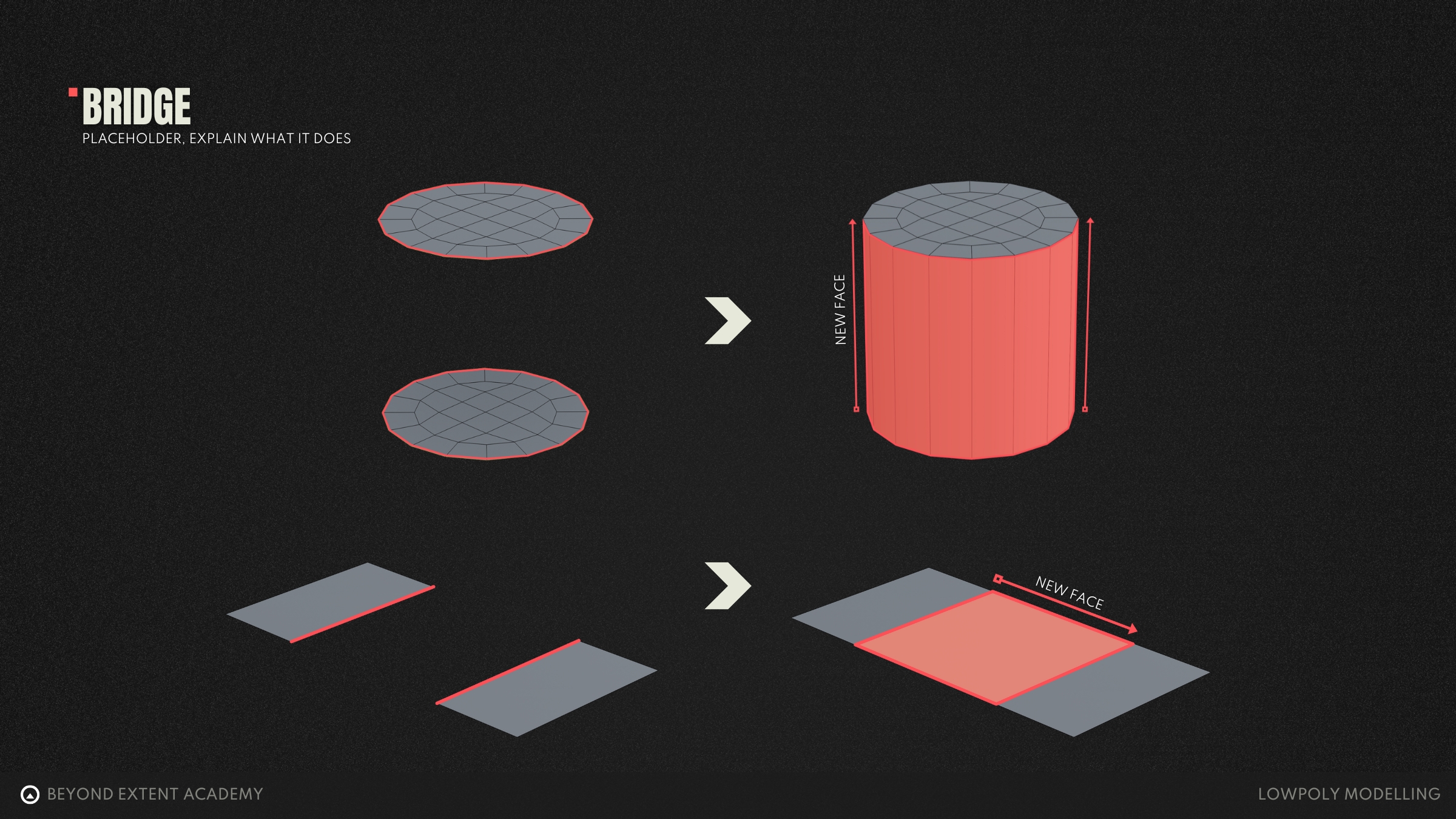
Bridge
Bridge connects two open edges or face selections by generating new faces between them. It's useful for filling gaps, closing holes, or creating transitions between separate parts of a mesh.
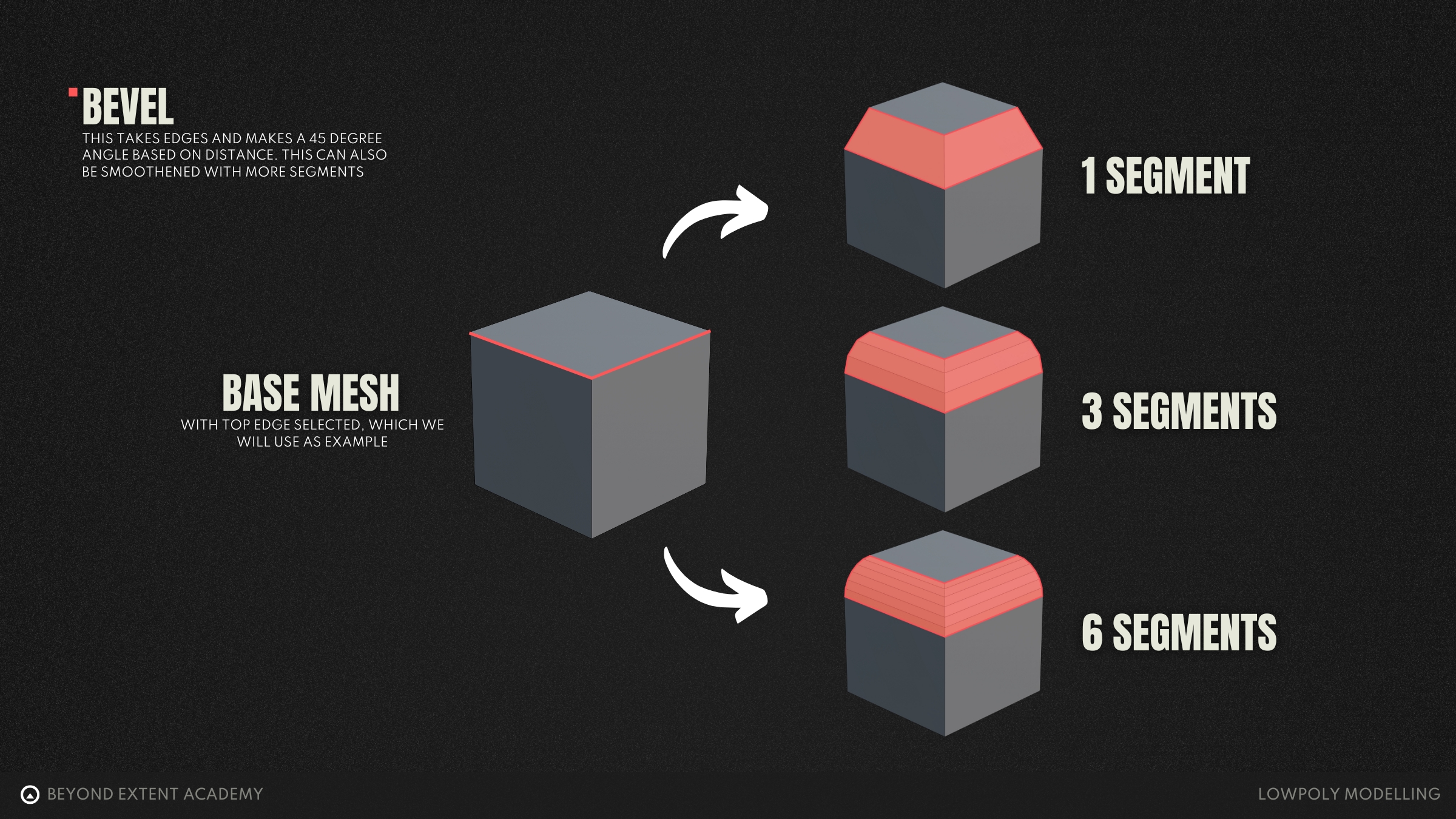
Bevel
Bevels help remove sharp edges by creating extra faces between them, making models feel more realistic. You can control how smooth the bevel is by adjusting its size and the number of segments. A single-segment bevel is often called a chamfer.
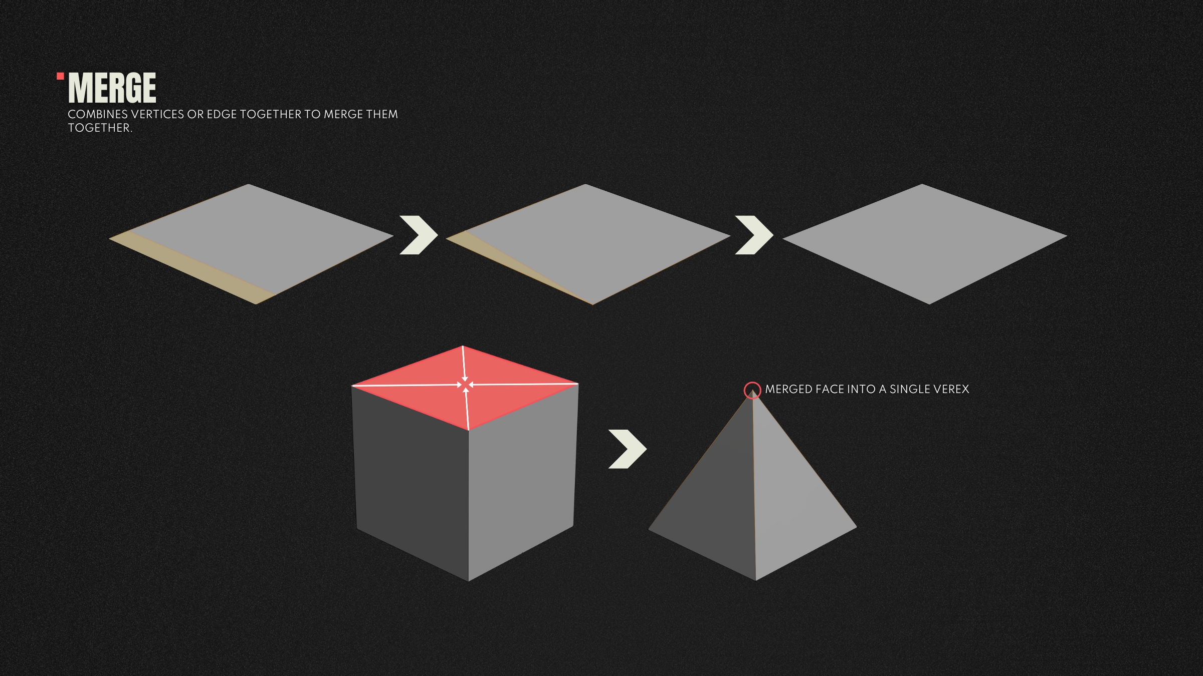
Merge
Merge combines selected vertices into one, removing overlaps or cleaning up geometry. It's commonly used after duplicating, bridging, or when simplifying complex areas of a mesh.
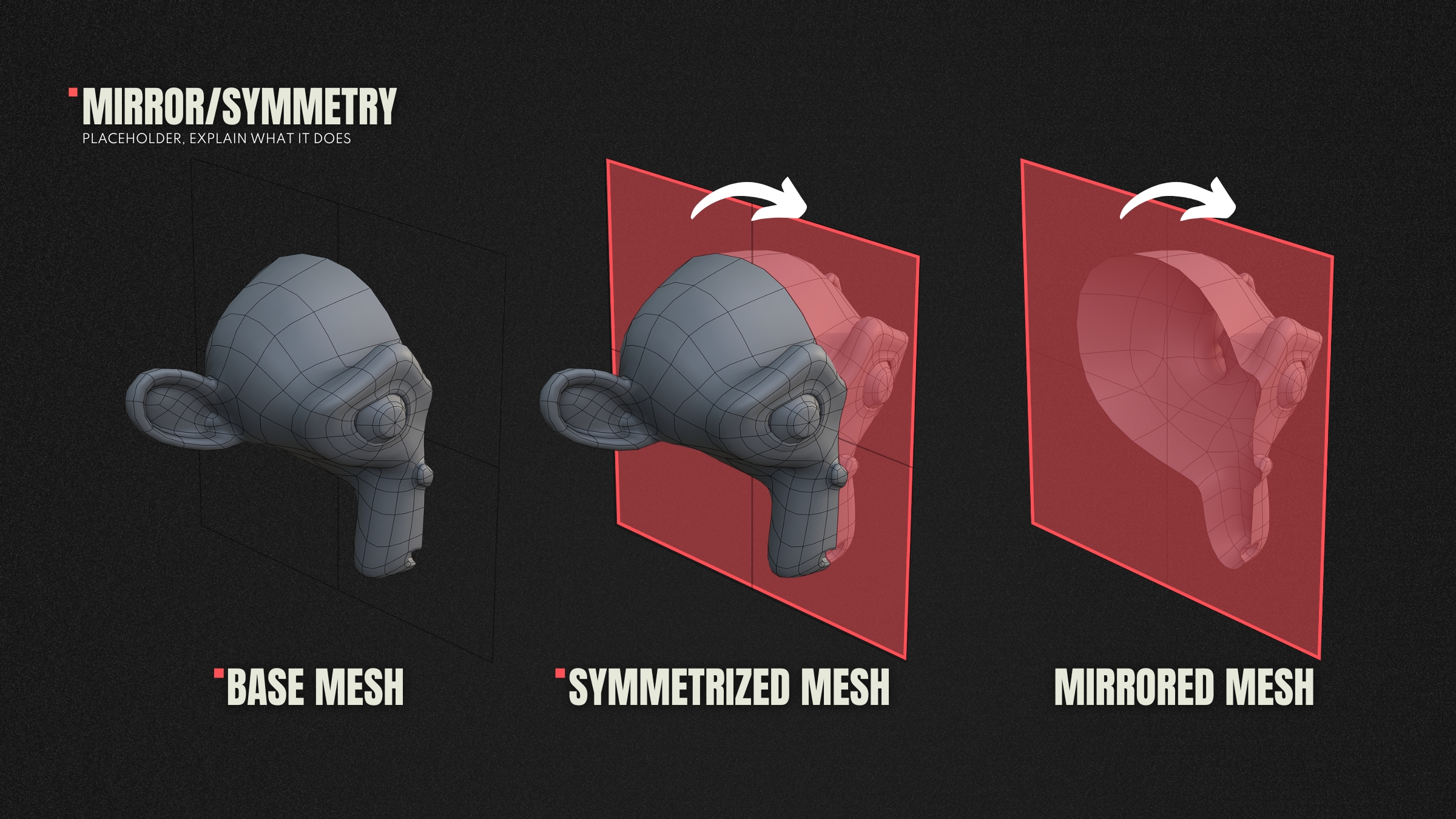
Mirror
Many objects are symmetrical, especially in character and prop design. The mirror operation duplicates geometry across an axis (usually left/right), saving time and ensuring symmetry. You only need to model one side, and then you can mirror it across to the other.
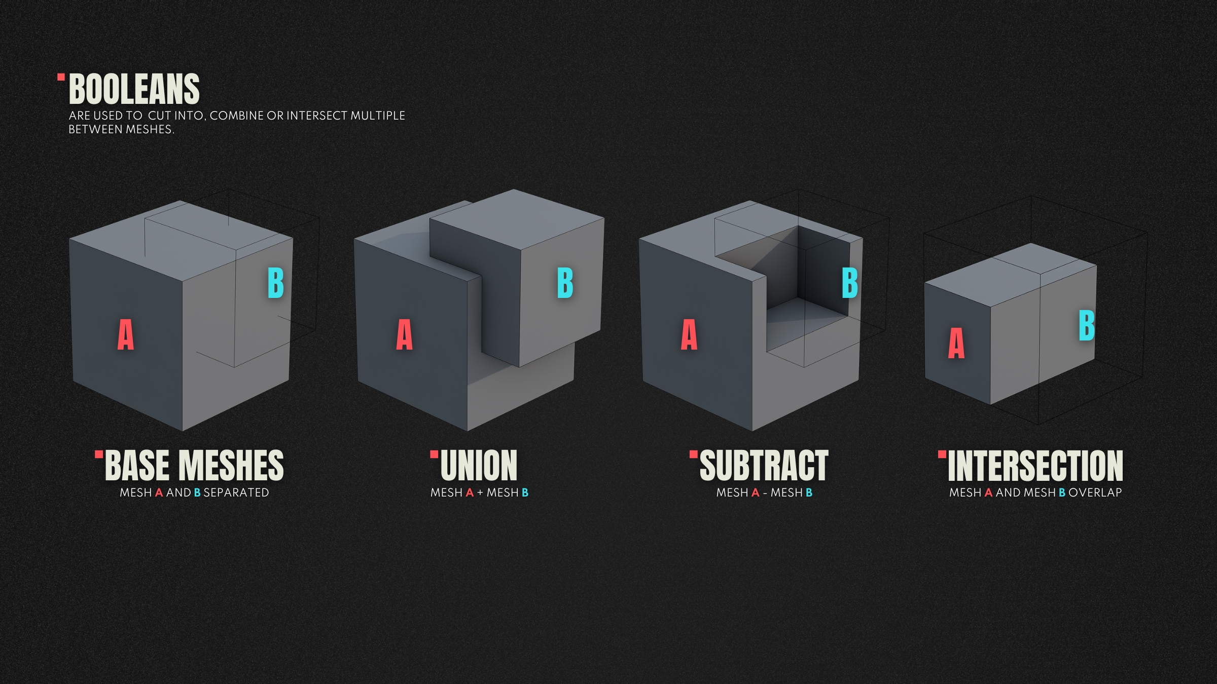
Boolean
Boolean allows you to combine, subtract, or intersect one mesh with another. It is great for creating complex forms like holes, cuts, or panelling. Booleans are powerful but can leave messy topology if not cleaned up properly afterwards using tools such as merge.
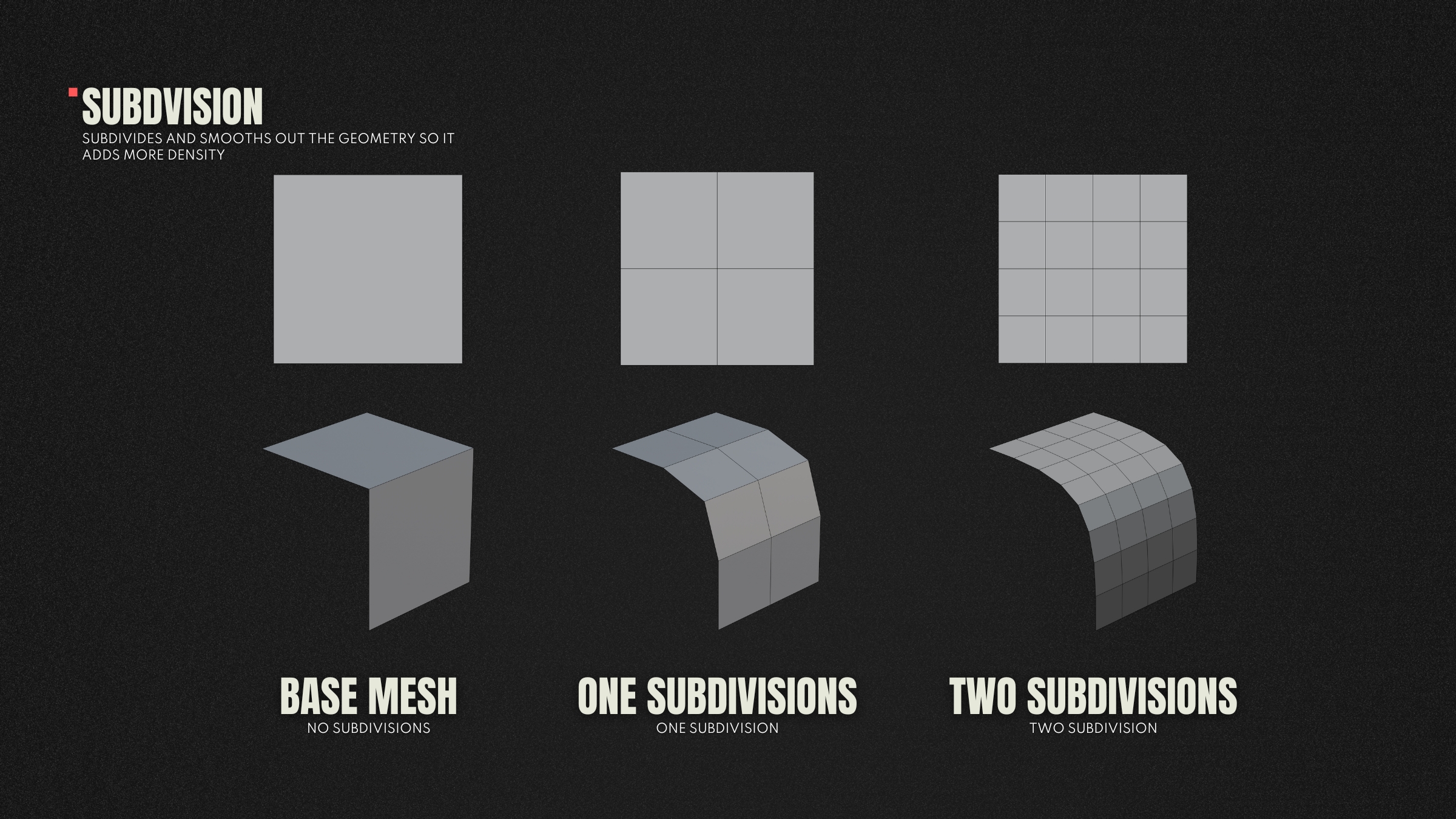
Subdivision
Subdivision smooths out geometry by dividing faces into four smaller ones. It’s used to create organic or rounded shapes and is typically applied with a subdivision modifier to maintain flexibility during the modelling process.
Subdivision smooths out geometry by dividing faces into four smaller ones. It’s used to create organic or rounded shapes and is typically applied with a subdivision modifier to maintain flexibility during the modelling process.
Modifiers
Modifiers are non-destructive tools that allow you to apply modelling operations to your model without permanently altering the base geometry. 3ds Max and Blender both include a modifier stack. Common modifiers include subdivision surface, mirror, Booleans and bevels. Using modifiers helps to keep your workflows flexible and reversible, ideal when iterating on designs and responding to feedback.
COMMON ISSUES
Sometimes, during the modelling process, mistakes can happen, whether that be through accidental edits or broken operations. When left unresolved, these issues can cause problems. Fortunately most DCC software includes tools to help identify them.
Detecting ngons
Ngons are faces with more than four sides, these triangulate unpredictably and lead to visual issues during rendering, especially on curved surfaces. It’s best to convert these to triangles and quads using the knife, loop cut and merge tools.
Most 3D software includes selection tools to highlight Ngons:
- In Blender, you can use “select all by trait > Faces by sides”.
- In Maya, you can use the “cleanup” window, and use “Faces with more than 4 sides”
- In 3ds Max, you can use “selection” and use the “by numeric” tool, to select faces with more than 4 sides.
Non Manifold Geometry
When a model contains geometry made up of problematic shapes that do not define a well-formed solid object, it’s known as non-manifold geometry. Usually this is due to edges or vertices being shared in ways that break a mesh’s integrity, such as edges shared by more than two faces, or edges that have zero length. It can’t be shaded or edited properly because the software can’t tell which way is "outside" or "inside”.
As with ngons, DCC software will have tools to identify, and sometimes clean-up non-manifold geometry for you.
- In Blender, you can use “select all by trait > non-manifold geometry”. Although this is only for vertex and edge selection.
- In Maya, you can use the “cleanup” window, and check “non-manifold geometry”
- In 3ds Max, you can use ****the “xview” menu to identify some types of non-manifold geometry, however 3ds Max will not allow the creation of certain types of non manifold 3D geometry.
Common non-manifold geometry types
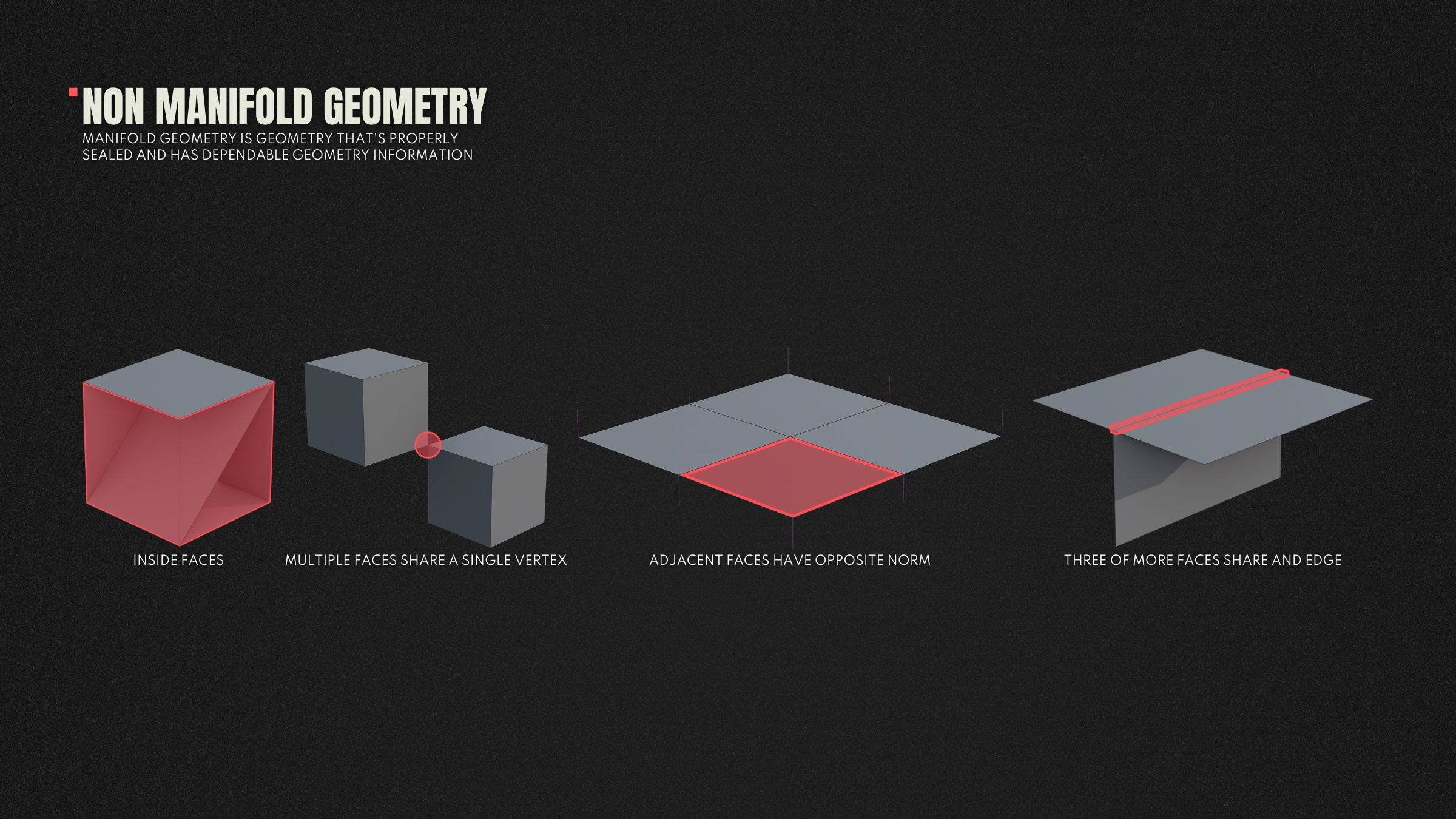
Multiple faces share a single vertex
This can happen when vertices get merged together accidentally.
Fix : Check the surrounding geometry and separate one part of the mesh if possible.
Adjacent faces have opposite normals (flipped normals)
You may see inconsistent shading, or black faces when normals are reversed. This can happen when scaling meshes, bridging, or accidently flipping normals.
Fix : Select the affected faces and flip their normals to match adjacent geometry.
Inside Faces
Sometimes extra faces can exist inside a model, especially after extrusions, combining meshes, or accidently using bridge / fill operations.
Fix : Manually delete internal faces.
Three or more faces share an edge
This often occurs after merging or bridging errors.
Fix : Manually delete or separate overlapping geometry until only two faces share any edge.
UV MAPPING
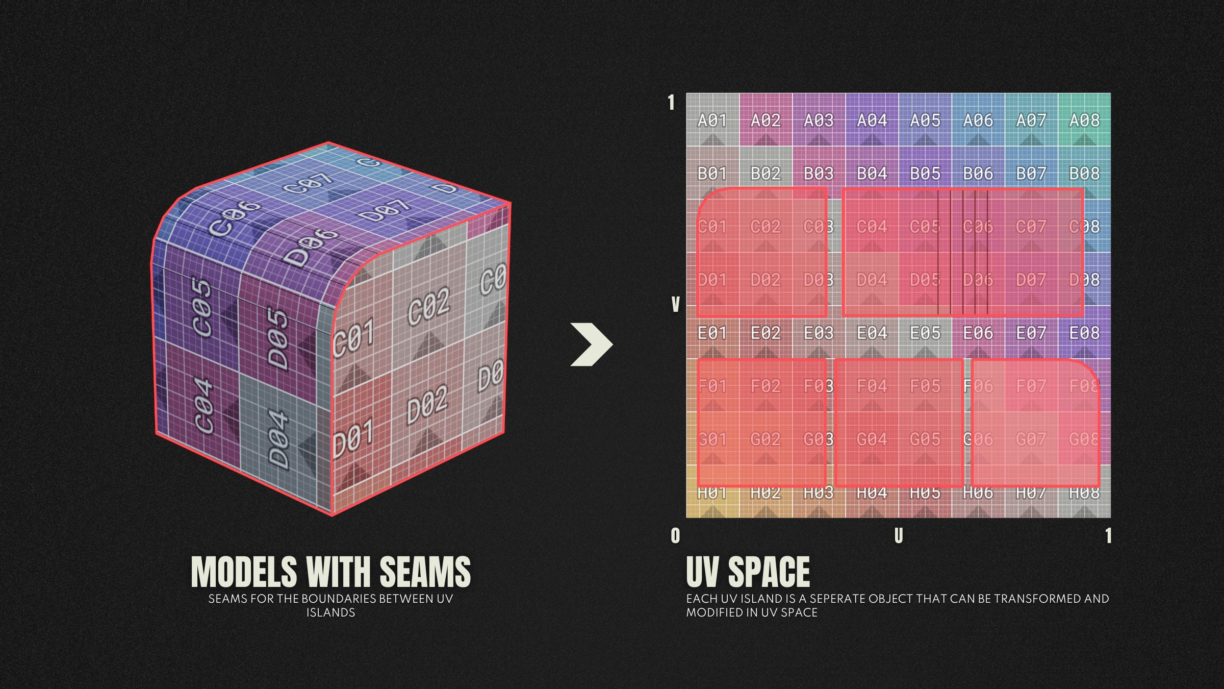
If we jump back to the start of the lesson, we learned that vertices can contain a number of attributes important to a 3D model. One of these was vertex normals. Another, equally important, is UVs. UVs stand for U and V, which are the two axes of the 2D texture space. Just like the Cartesian coordinates X, Y, and Z define 3D space, U and V define the horizontal and vertical axes of 2D space.
To break it down as simply as possible: UV mapping is the process of taking a 3D model’s surface and laying it out as a flat, 2D representation. This allows us to apply textures to the model accurately.
For a deeper dive into UV mapping, check out the following lesson [UV Mapping lesson]
FORMATS
When it comes to finishing your 3D model, you’ll want to export your model as a single file for it to be used in other applications, such as other modelling software, games engines, or maybe even 3D printing.
There are a wide number of file formats you can export your model as, but these are the most common :
- .FBX - This is the most widely used format in games and film, it supports mesh data, animation, cameras, lights and more. It’s great for moving assets between DCC tools and game engines.
- .OBJ - Probably the next most common in games. This only supports static geometry and stores all the same mesh data, but no animation or advanced materials.
- .STL - This is a simple format used mostly in 3D printing, it contains only geometry with no materials or colour data.
- .GLTF / .GLB - This is an optimised file format for realtime applications such as web or AR. It supports materials and animation.
- .USD - Universal Scene Description is a file format developed by Pixar. This supports complex scenes and non-destructive workflows, used in film, VFX and realtime pipelines.
exercise
Lowpoly Modelling - Exercise 01

Lowpoly Modelling - Exercise 01
overview
In this exercise, you will be exploring how to use the previous sections in this lesson and how to apply them. Starting from using simple primitives and then refining the shapes using modelling techniques and modifiers.
lesson example content
Get into it instantly by downloading the starter content for this lesson
download lesson content